This is to illustrate aspects of this transformation of edges. As descrbed in Thirty Edge Transform Part 1, edges of an Icosahedron can be simultaneously rotated about lines from their midpoints to the center, passing through a sequence of skew orientations, some orientations that align in sets of parallels, and some that align in planes that occur as polylinks. The focus here is on filling out the profiles of the rotated edges as they align as polylinks, to form prisms with facets that meet facets of adjacent prisms in the array.
A 3D design created in vZome. Use your mouse or touch to interact.
The various configurations formed by the 30 sticks are chiral, occurring in both right and left handed form in the full sequence. In the model shown above, the default scene shows both chiral forms filled out, combined. Scenes shows a seqeunce from the transformation which includes two skew orientations of sticks, represented just by struts, one just before the intersection as triangles, and one just after. The significance of these positions is this; For many years I and others worked with constructions of simple parts, sticks and some form of tension elements pulling them toward each other as they pass by in various configurations. In this sparse way of building, intersection of sticks is disallowed as an interruption of continuity, requiring some alteration, like notching, deflection, etc. Basicallly, two things can’t be in the same place at the same time. So to build a triangle, 3 sticks pass by each other and the vertices of the triangle are defined by the points between the sticks at their closest distance from each other. If they are in contact, the vertex points are where they touch. For a full Icosahedron, there is a structure of 30 sticks that pass by each other symmetrically, and for configurations like the 10 triangle interlink, there is typically a structure of bypassing rods just before the intersection, and one just after, in the sequence of rotation, starting from Icosahedron. Below are images of both of these, corresponding to the ones shown in Scenes. Note that they are of opposite chirality to the ones in the model. The first is 10 triangle interlink “before intersection”, the second is 10 triangle interlink “after intersection”.


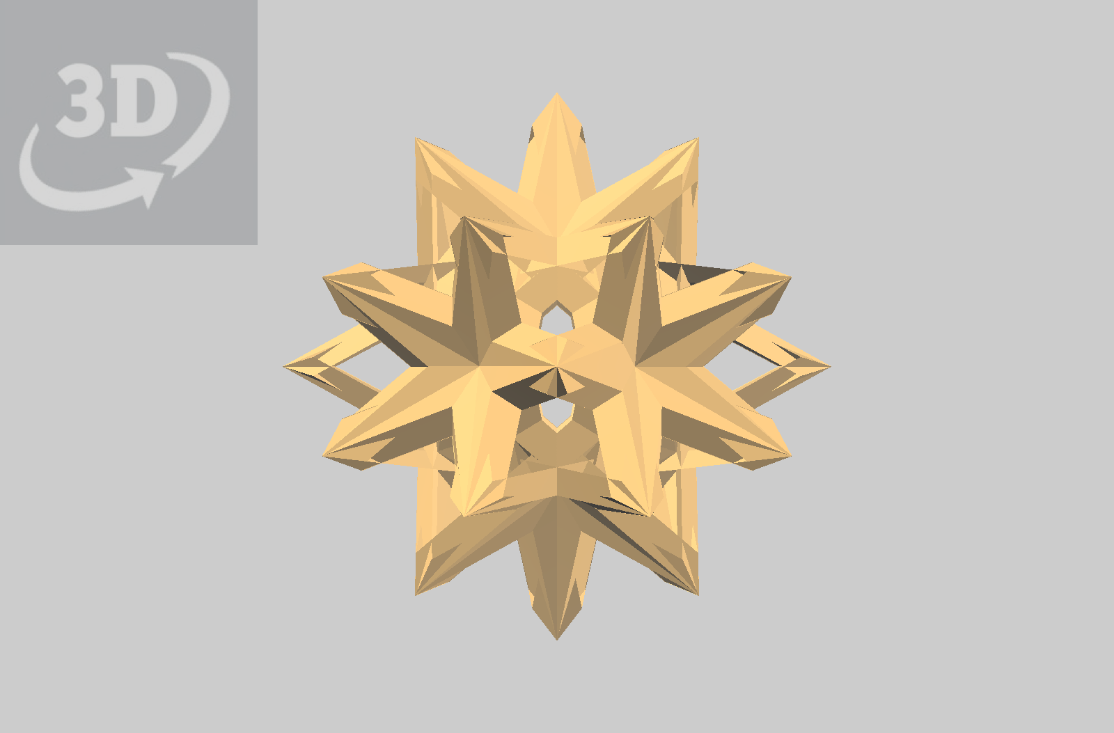
In the transformation sequence, the next planar intersection is the five Tetrahedron interlink, shown below. As with the model above, the default scene is both chiral forms, fully filled out, combined. Scenes shows two skew orientations in which structures can be composed, one just before the intersection as tetrahedra, and one just after. These are extraordinary structures. In this model, the skew sticks are filled out to the profiles that contact with the adjacent sticks in the array.
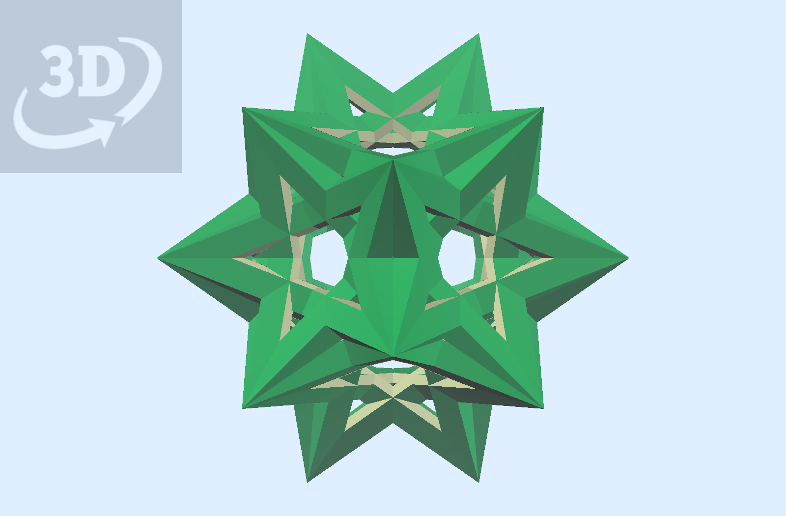
Below is an image of a 5-tetrahedron interlink constructed with bypassing rods, corresponding to the “after intersection” model in Scenes. Note that it is of the opposite chirality.

Below is a model of the next configuration in the sequence, where the struts are rotated to a coplanar alignment, forming six interlinking pentagons. As in the above models, the sticks are filled out to a profile that meets the adjacent sticks in the array. The default scene shows a combination of the two chiral forms.
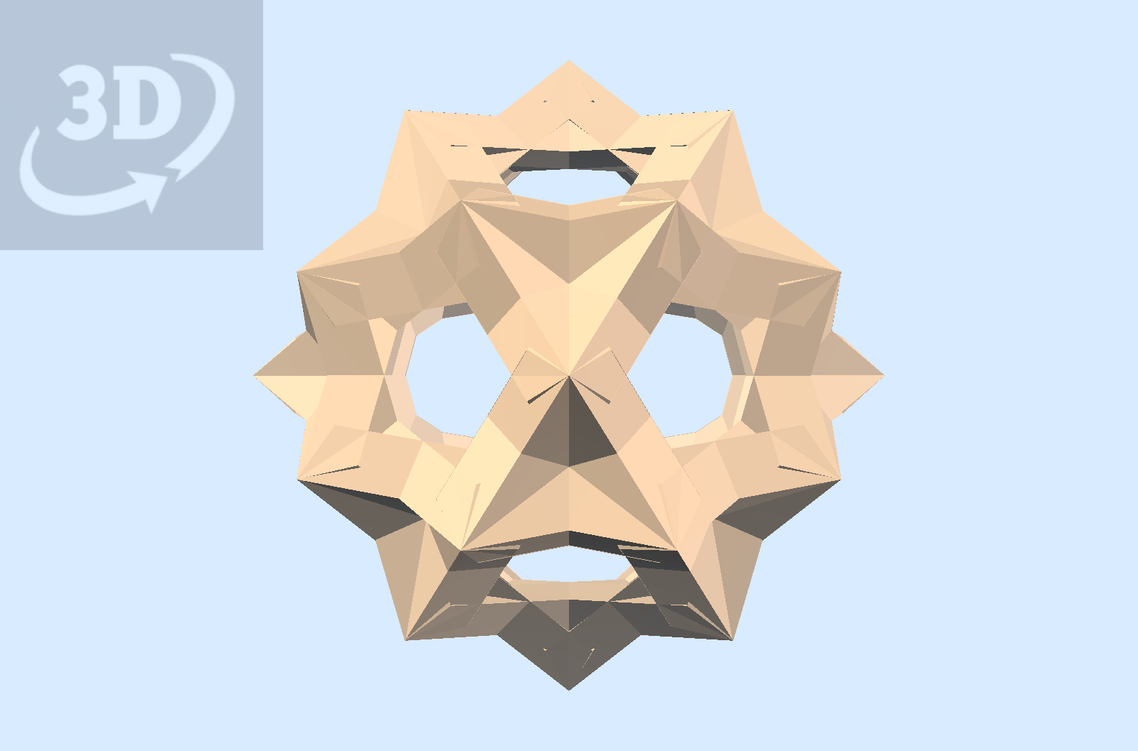
In addition to the six pentagonal rings and six pentagrams, Scenes shows two skew orientations, filled out. They represent structures that can be made with bypassing rods. An image of one such structure is shown below. It corresponds to the “After intersection” model.
